ADI’s ADEPT Framework now supports Modbus TCP for use in Real-Time Linux servers. Modbus TCP is a data communications protocol originally used with industrial programmable logic controllers (PLCs). Modbus TCP has become the de facto standard communication protocol commonly used to connect industrial electronic devices, making it a great addition to ADI’s ADEPT Framework and real-time Linux servers.
What is Modbus TCP?
Modbus is a data communication protocol first published in 1979 for use with programmable logic controllers (PLCs). Modbus popularity is driven by being openly published and royalty free. Originally used in industrial applications using serial line communication, Modbus has expanded to be used with Ethernet or the Internet protocol suite as a transport layer and is now a commonly available means of connecting industrial electronic devices. It is relatively easy to deploy and maintain compared to other standards while placing few restrictions, other than the datagram size, on the format of the data to be transmitted. Modbus TCP supports communication to and from multiple devices connected to the Ethernet network.

Modbus is often used to connect a plant/system Supervisory Control and Data Acquisition (SCADA) system with factory electronic devices. In Modbus, many of the data type names are derived from industrial control of factory devices. For example, a single output is called a coil (1 bit) and a single input is called a discrete input (1 bit). Other types include the input register (input data) and holding register (output data), both 16 bits. There are no 32-bit types; 32 bit floating and long integer data types can be handled by using 2 input registers or 2 holding registers.
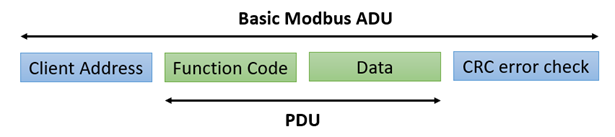
Modbus TCP uses client/server terminology. A client actively polls for data from one or more servers. A server is a passive component, sending data upon client request. A basic Modbus Application Data Unit (ADU) consists of 4 elements: Client address, function code, data, and CRC error check.
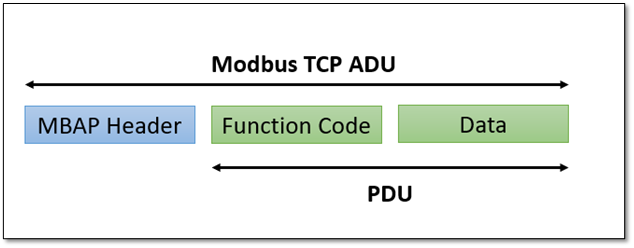
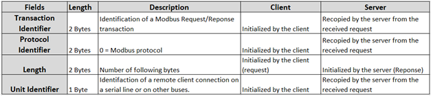
In Modbus TCP, the server address and CRC error check are replaced with a Modbus Application Protocol (MBAP) header. The 7-byte MBAP header consists of a Transaction Identifier, Protocol Identifier, Length, and a Unit Identifier, shown in the table below.
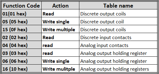
The client that initiates a Modbus transaction builds the Modbus TCP ADU. The function code indicates to the server which type of action is to be performed. Examples of common function codes are shown below. Refer to each device for specific function codes or refer to Modbus.org for more details.
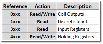
The Modbus memory locations of a device are organized around the 4 basic data types. These are shown below.
Below is an example of a Modbus TCP request for the content of an analog output holding registers #40108 to #40110 from the server device with address 15.
00 01 00 00 00 06 15 03 00 6B 00 03
00 01: Transaction identifier
00 00: Protocol identifier (Modbus = 0)
00 06: Message length (6 bytes to follow)
15: The unit identifier
03: The function code (read analog output holding register)
00 6B: The address of the first register requested (0x6B = 107 + 40001= 40108)
00 003: The total number of registers requested (3 registers 40108 to 40110)
The server would respond with the content of registers 40108 to 40110.
ADEPT and Modbus TCP
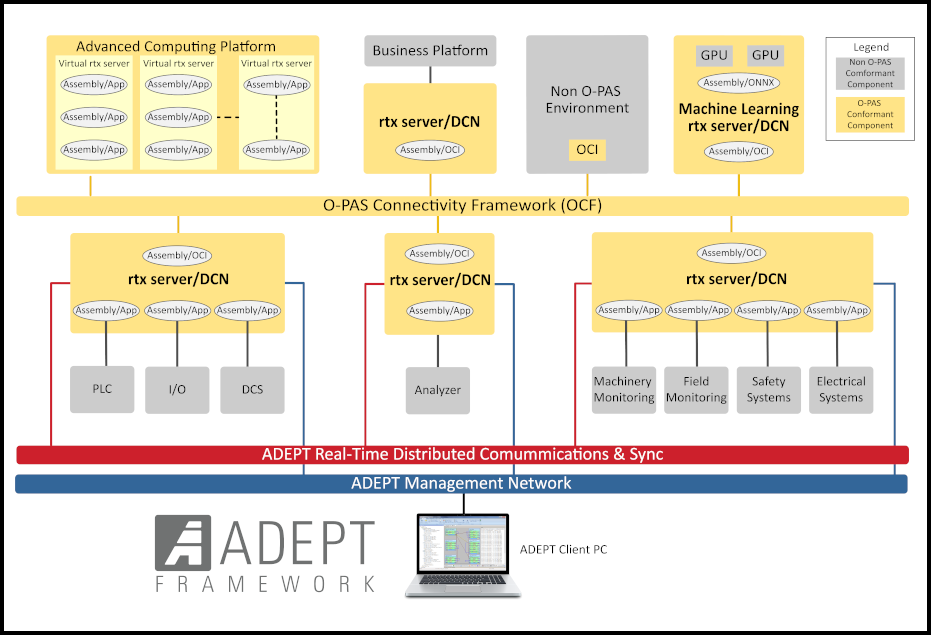
ADEPT enables industrial real-time Linux server deployments that support distributed and accelerated computation through all stages of product development, supervisory control, verification testing, demonstration, and training. By leveraging commercially available off-the-shelf (COTS) and open hardware components, ADEPT enables extremely high-performance cyber-physical systems with industry leading support.
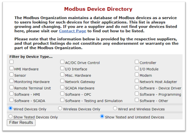
Combining industrial real-time Linux servers with Modbus TCP brings the power and flexibility of Linux real-time servers to the world of industrial automation, motion control, and data acquisition systems. A list of Modbus devices can be found in the Modbus Device Directory at https://modbus.org/devices.php.
Case study: Temperature Sensor
In the ADEPT Framework, setting up a Modbus Client can be accomplished in just a few steps using the ADEPT Development Environment (ADEPT-DE).
Step 1: Create a framework, Modbus_TCP_Example, then add a project, Temp_Monitor, to the framework.
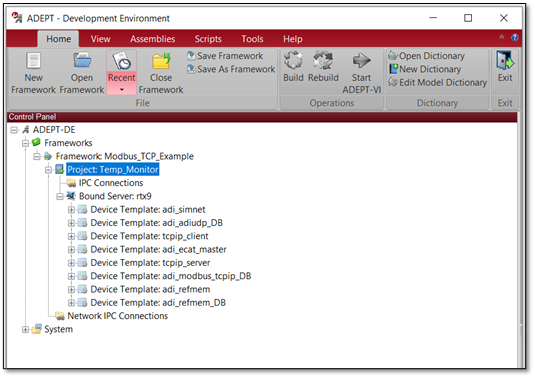
Create a Framework and Add a Project
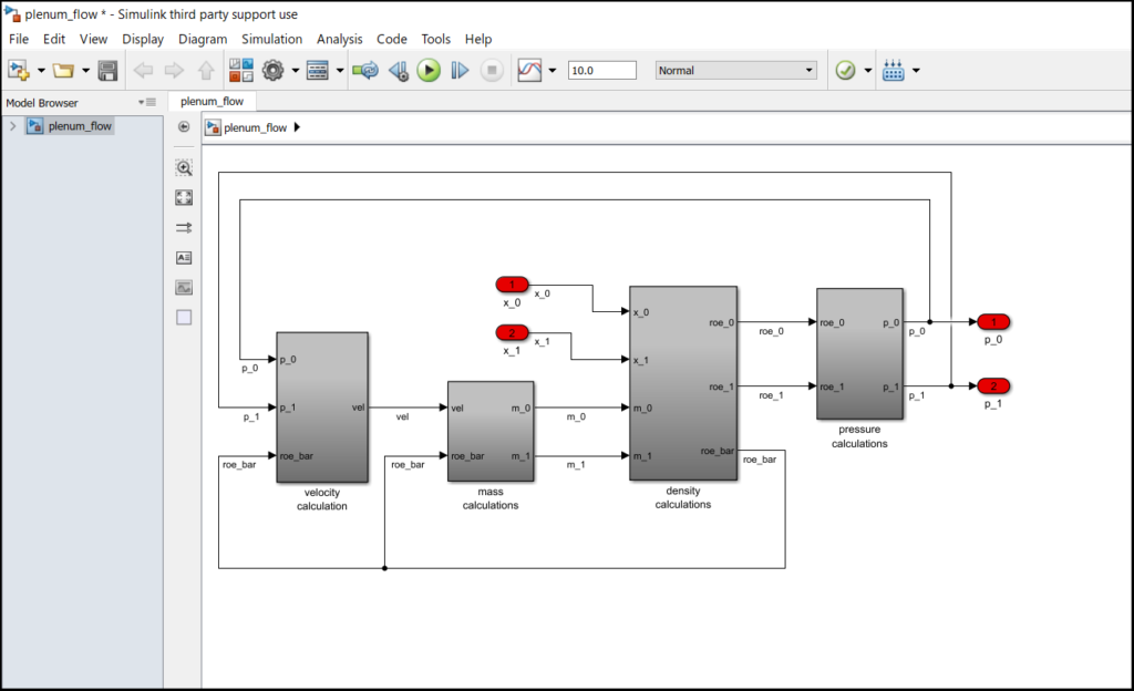
Step 2: Add a Model Assembly. Model assemblies are containers for models. In ADEPT, model assemblies can contain C code (as in this example named Modbus_TCP_Client), Simulink, ADSIM, C++, or an FMI/FMU model.
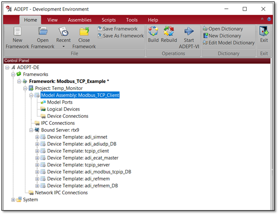
Add a Model Assembly
Step 3: Drag the adi_modbus_tcpip_DB device template, from the Bound Server, rtx9, and drop it into the Logical Devices for the autogen Model Assembly. Connect the ports in the logical devices to the corresponding model ports. The device status port returns a value corresponding to the status of the communication. For example, a value of 0, indicates no TCP connection has been made. The enable_recovery port, if set to 1, initiates recovery of the TCP connection. More details on these ports can be found in the Modbus TCP section of the ADEPT Help.
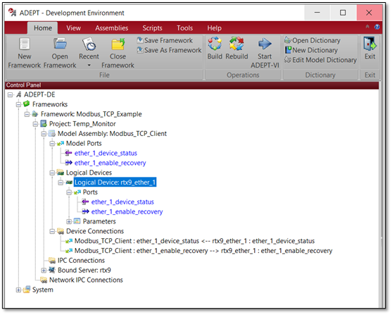
Add the Modbus logical Device to the Model Assembly
Step 4: Configure the Modbus logical device. To configure network devices in the ADEPT framework, create a CSV file to configure the network device and a dictionary file to allocate memory.
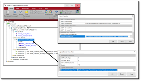
Dictionary and CSV files in DE
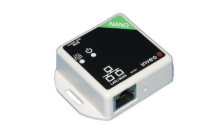
The CSV and dictionary files are created using ADEPT-DB. ADEPT-DB is a tool to create and manage message definitions for networked systems of various protocols. For this example, the server is a Nano temperature sensor.
In the temperature sensor the temperature consists of 32 bits. In modbus TCP 32-bit information is handled using 2 requests for holding register data, each 16 bit. One request for the decimal portion of the temperature and one for the integer portion of the temperature.
Since this is a request for 16 bits (2 bytes) the function code is 03 – Read Holding Register. These are shown in lines 1 and 2 below. The response from the temperature monitor will also be function code 03 messages, show in line 3 and 4 below.
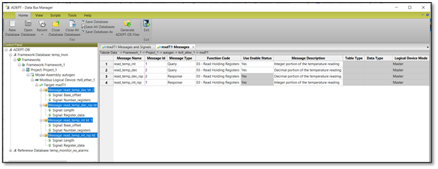
ADEPT-DB Message Definitions
Each request message will contain 2 signals, the base memory offset of the data register and the number of registers to be read. The response messages will also contain 2 signals, the register data, and the length. This is shown below.
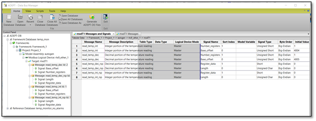
ADEPT-DB Signal Definitions
Once the messages are defined in ADEPT-DB, the CSV and dictionary files used by ADEPT are generated. The framework project in ADEPT-DE can be built and then run in ADEPT-VI.
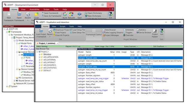
Build and Run in ADEPT-VI
Using the ADEPT Framework, industrial Linux Server, and Modbus TCP offers an easy environment to create a Modbus client or server for your industrial control project.
Conclusion
With ADEPT and industrial real-time Linux servers, it is easier than ever to implement Modbus TCP-based systems with the latest MBSE tools. Leveraging built-in support for C/C++, Simulink, ADSIM, andFMI/FMU models, the ADEPT Framework enables MBSE practices for industrial automation, motion control, data acquisition, and real-time control systems using Modbus TCP.
How can the ADEPT Framework supercharge your Modbus TCP network? Contact your local ADI representative today to see how the ADEPT Framework and industrial Linux servers can improve the quality and efficiency of your development process.