Introduction
Applied Dynamics International (ADI) recently completed the Digital Twin and Open Automation for Process Manufacturing project. The primary objective of the project was to demonstrate viable proof-of-concept Digital Twin and Open Automation solutions for use in the process industry in alignment with these principles:
-
- Collaboration
-
- Collaborative platform for generating value.
- Cost Effectiveness
-
- Lower cost of embracing digitization without disruption to production facilities.
- Risk Management
-
- Minimize the overall risk for process industry and extend application of proven digital technologies beyond discrete manufacturing.
- Innovation
-
- Broaden innovation scope by engaging solution/service providers and end-users at the early stages of technology development and evaluation.
- Advancement/System Integration
-
- Accelerate screening, piloting, and adoption of digital tools/technologies (sensors, cybersecurity, data analytics, etc.).
- Best Practices
-
- Jointly address unique operational and regulatory requirements of process industries, e.g. safety requirements, process optimization, and process disruption avoidance.
- Work Force Development
- Provide workforce training for the “factory of the future.”
The Process Manufacturing Digital Twin – Open Architecture Testbed Framework consists of a digital twin and open automation sandbox with a self-contained Integration Test Environment (ITE) platform. This combined system and software platform demonstrates and evaluates digital twin and open automation technologies with cross-vendor systems. It also allows for manufacturers to develop, test, and evaluate new technologies, without interrupting production operations, and without costly R&D investments. The user interface panels in Fig. 1 provide access to the DT & OA applications (shown on the left) and a factory emulator framework (on the right).
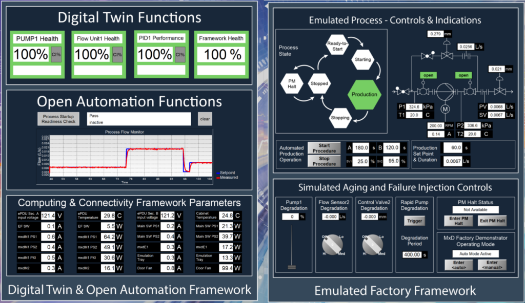
Figure 1: Digital Twin & Open Automation Framework Interface Panels
DT & OA capabilities benefit manufacturers and other heavy industrial organizations looking to:
- gather and analyze all data from their manufacturing line or industrial facility necessary to improve visibility and control of the manufacturing process.
- leverage advanced technology, such as mobile worker, cybersecurity, predictive maintenance, and other digital twin use cases.
as well as current users of ADEPT or ADvantage in laboratory or test facilities, looking to leverage their real-time networking and control experience base in a modern manufacturing context.
How ADEPT facilitates DT & OA Development & Deployment
Several key strengths of the ADEPT platform make it a great fit for DT & OA development and deployment:
-
- Flexibility
- ADEPT’s industrial computing and data handling “framework” paradigm enables models to be easily added, assigned to processing resources, connected to data and saved as a framework instance to support an unlimited set of operating modes and equipment/models included within the scope of operation.
- Data Centric, Distributed Architecture
- ADEPT provides a comprehensive overview of the data within models, coming from equipment, and moving through the deployment.
- Cybersecurity
- ADEPT’s Linux real-time computing capability enables the testbed to leverage existing cybersecurity hardening policies.
- Computing Efficiency
- Through decades of code refinements and optimizations, the ADEPT server code reduces the cost of computing hardware by getting more out of the same CPU(s).
- Faster Deployment
- ADEPT reduces the engineering and IT effort to assemble an industrial computing and data handling capability using plug-and-play interaction.
- Flexibility
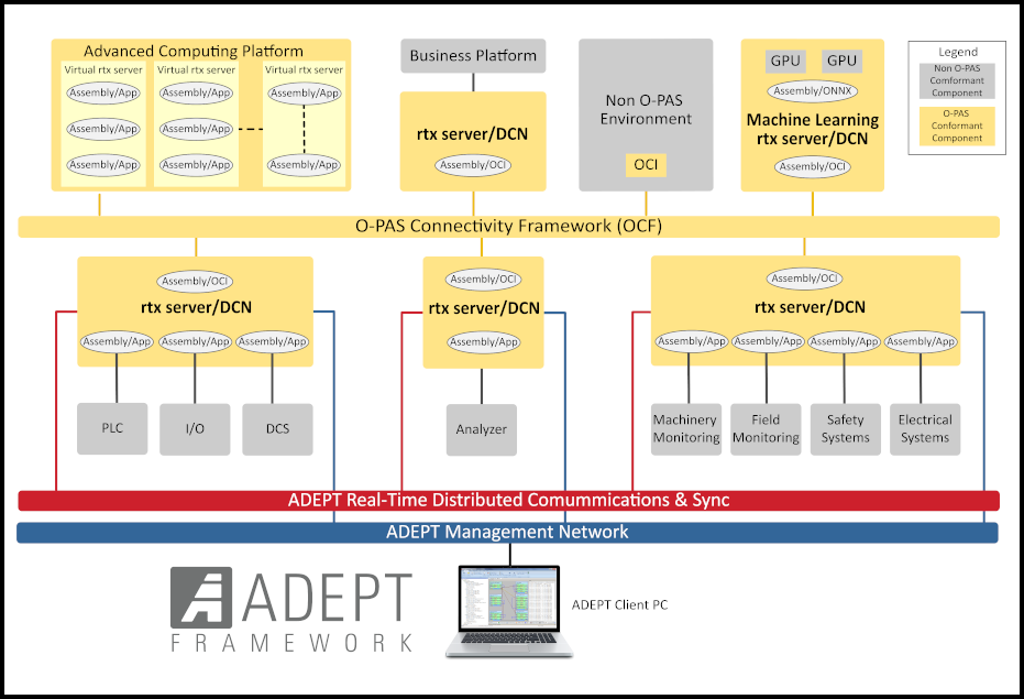
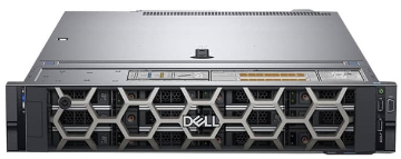
A real-time computing and data-handling framework is made up of one or more real-time Linux servers operating in coordination, and with time synchronization. The real-time framework provides a flexible computational structure, allowing these Linux servers to be interfaced with the real world, i.e. equipment, PLCs, sensors, actuators, data acquisition devices, etc., and operated as a time-synchronized cyber-physical system. Typical servers utilized, along with descriptions of their roles, are displayed in Tbl. 1.
Table 1: Typical servers used in an ADEPT real-time framework
| High-Performance Servers | |
|---|---|
|
Dell PowerEdge Series
|
 |
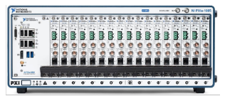
| High-Density I/O Connectivity | |
|
PXI/PXIe industrial computers
|
 |
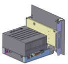
| Low-Cost Servers, DIN-rail-mounted | |
|
Nvidia Jetson-Xavier
|
 |
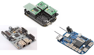
|
ARM: BeagleBoneBlack, BeagleBoneBlue, TI-ICE
|
 |
Process Manufacturing ITE
The digital twin, open automation, and emulator capabilities of the Process Manufacturing ITE are split across two main frameworks: one framework that handles the digital twin and open automation capabilities and a second framework that handles the process emulation. The emulator framework contains several assemblies used to generate simulated process data, package those data into industry standard communication protocols, and send those data across the ITE network. The data are then transferred via several dedicated data protocol interface assemblies within the DT-OA framework, and used by the digital twin and open automation assemblies to monitor process and equipment health.
Each framework runs on a separate server or collection of servers. The DT-OA framework runs entirely on a Dell PowerEdge R540 server, while the Emulator framework is distributed across four different servers: one Nvidia Jetson AGX Xavier and three Texas Instruments AM3359 Industrial Communications Engines (TI-ICE). The Nvidia Jetson AGX Xavier hosts the physics-based process simulation model and another model that packages certain data elements into OPC-UA packets to be sent to the DT-OA framework, while the TI-ICE’s package the process simulation data into ModbusTCP packets to be sent to the DT-OA framework.
OA factory process modeling with Simscape and ADEPT
About Simscape
Simscape ® is a physics-based modeling tool, using the across/through classification of power-conjugate modeling variables introduced by Firestone in 1933 [1], and further developed by Trent in [2] and Blackwell in [3]. It was first released by Mathworks in 2007 as an extension to the Simulink block-diagram modeling tool, and new versions are released twice per year, in synchronism with new releases of Matlab and Simulink. Simscape diagrams bear a strong resemblance to electrical circuit diagrams, reflecting Firestone’s original intent to represent mechanical systems using electrical analogies.
In Simscape, physical components are represented by icons with ports where across- and through-variables are defined for particular physical domains, such as electrical or mechanical. Multiple interacting domains can be represented on the same diagram. Icons sharing the same connection line have common across variables (those analogous to voltage), and their through variables (those analogous to current) add when connections branch. This logic produces generalized Kirchoff circuit laws for each physical domain in the model, and allows the differential equations for the model to be automatically derived by Simscape, once the component parameter values and connections are fully defined. This relieves the analyst of the burden of deriving the differential equations, allowing him to concentrate on the physics of the problem, and producing thereby a more rapid modeling iteration rate. This in turn reduces the cycle time required to converge on a model competent to represent the desired physical effects.
Simscape interoperates with Simulink, which can produce Simscape inputs, and can accept Simscape outputs. Simulink Coder can generate C and C++ code from combined Simulink/Simscape models, for real-time and nonreal-time applications, including hardware-in-the-loop testing. ADEPT’s support for importing Simulink model assemblies, which relies on Simulink Coder, is sufficient to also allow import of combined Simulink/Simscape model assemblies.
Features of OA factory process model
A Piping and Instrumentation (P&I) diagram of the OA factory process model is shown in Fig. 2. The diagram illustrates a typical plant process, using pump PMP and control valves CV1, CV2 to transfer fluid at a controlled rate from tank Ti on the left, to tank To on the right. A tachometer on motor PM provides feedback signal MS, which is required to control the pump at a constant speed, high enough to satisfy the maximum flow demand. Flow meters FM1 and FM2 provide the feedback required to successfully operate the control valves, such that they produce the commanded fluid flow rate.
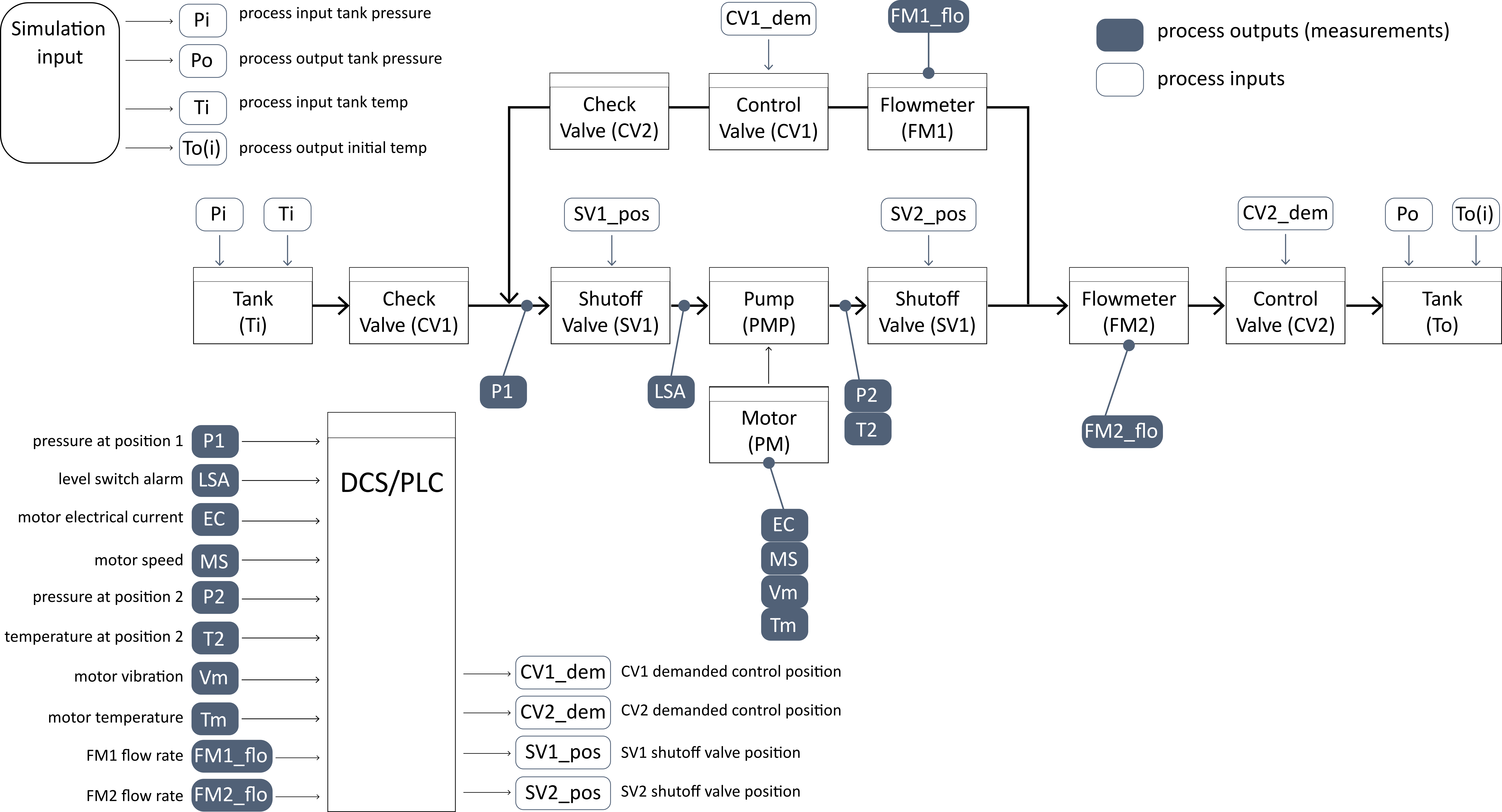
Figure 2: OA factory process P&I diagram
A simplified representation of this P&I diagram is also shown in the ADEPT panel on the right side of Fig. 1.
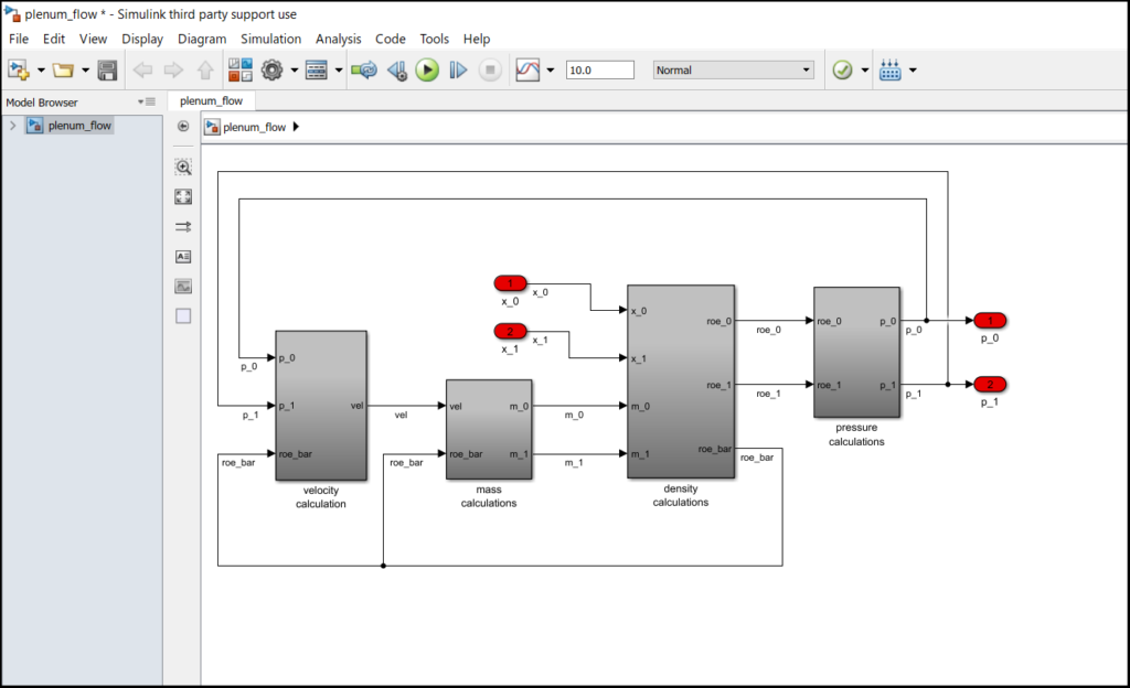
The Simscape portion of the Simulink model implementing the P&I diagram is shown in Fig. 3 (the figure is cropped on the right). Icons representing components operating in different physical domains are shown in different colors.
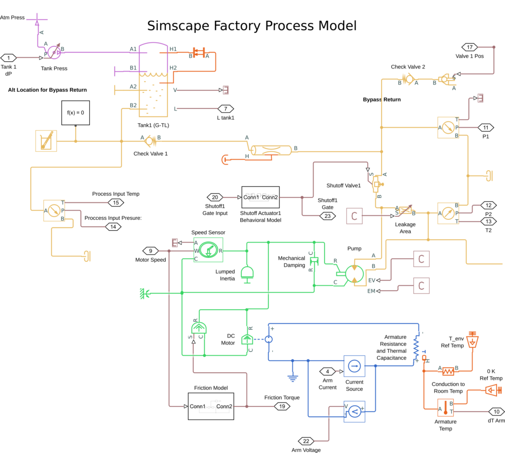
Figure 3: Factory process Simscape diagram (cropped on right)
In this diagram one can see icons, ports, and the lines connecting them, representing the following physical domains:
- the thermofluid domain, in gold;
- the pneumatic domain, in violet;
- the thermal domain, in orange;
- the electrical domain, in blue;
- the rotational mechanics domain, in green.
There are also a few black boxes representing signal-based subsystems, such as the friction and valve actuator behavioral model subsystems. These are constructed in a similar fashion to standard Simulink subsystem blocks, but the gains, summers, integrators etc. in these subsystems process Simscape physical signals, which standard Simulink components cannot do.
The continuous-time Simscape plant model in this diagram is a subsystem of an enclosing Simulink model that contains the necessary feedback control logic, which executes entirely in discrete-time, at a 100 Hz rate. There are separate control loops for the motor speed and the fluid flow rate. These are standard industrial-style proportional-integral (PI) controllers, with set-point weighting and integrator wind-up protection. Both control loops are designed to exhibit a 300 ms time constant in response to command changes.
OA factory process model results
The factory process model described above was imported into an ADEPT assembly running on a low-cost Nvidia Jetson-Xavier ARM target, with ADI’s run-time services hosted by an Nvidia-customized version of the Ubuntu 18.04 Linux OS. The ADEPT framework containing the process model was interfaced to the ADEPT panels illustrated in Fig. 1. This provided a user-interactive interface in which the process model could be sequenced through the process states illustrated in the panel on the right side of the figure, which are:
- Stopped,
- Ready-to-Start,
- Starting,
- Production,
- Stopping,
- PM Halt.
Fig. 4 displays the design intent for flow command and response during each of the process states.
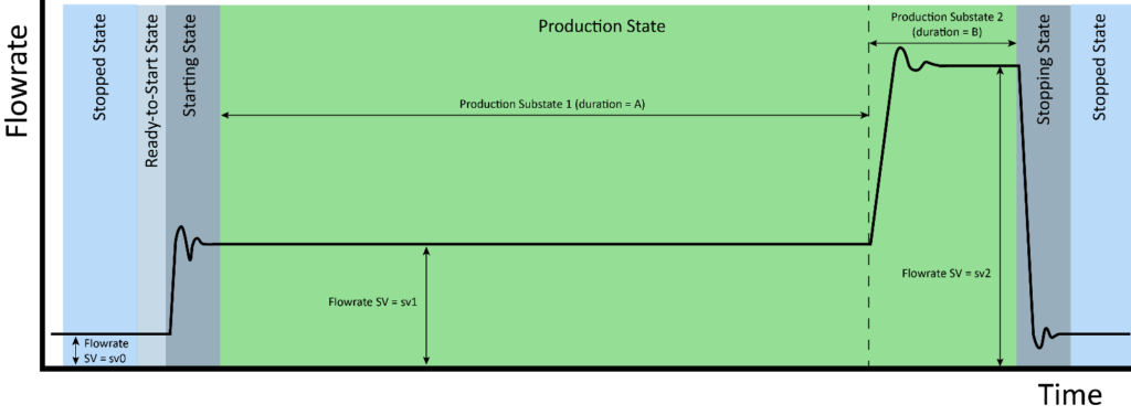
Figure 4: Flow command and response, design intent vs. process state
Actual transient responses of the flow control loop are displayed in the center of the left panel in Fig. 1. Note that the measured flow rate data contain simulated measurement noise. The loop response to step changes in flow command is well-approximated by a single dominant 300 ms time constant, as intended.
Process model design challenges
The nonlinear and numerically stiff nature of the differential equations describing fluid flow in the process model precludes using a fixed step size for the Simscape integration algorithm. This makes it difficult to guarantee the integration step will always complete within the allotted 10 ms frame time. Some model features were added (e.g. pump leakage), and some removed (e.g. fluid compressibility), to reduce frame overruns. The best numerical integration performance was obtained by consolidating all continuous-time modeling features into the Simscape subsystem, leaving Simulink to handle only discrete-time modeling features. Mathworks provides additional guidance for real-time simulation of Simscape models in a white paper available at their website [4].
Mathworks documentation also provides guidance on how to configure Simulink Coder to produce C code with symbolic parameters, thereby allowing those parameters to be interactively changed at run-time. It was found however that this guidance is not always effective for parameters of Simscape components. Generating C code that allows all desired plant parameters to be varied at run time, without regenerating the C code, remains a challenge.
References
[1] F. A. Firestone, “A new analogy between mechanical and electrical systems,” The Journal of the Acoustical Society of America, vol. 4, no. 3, pp. 249–267, 1933.
[2] H. M. Trent, “Isomorphisms between oriented linear graphs and lumped physical systems,” The Journal of the Acoustical Society of America, vol. 27, no. 3, pp. 500–527, 1955.
[3] W. A. Blackwell, Mathematical modeling of physical networks. Macmillan, 1968.
[4] S. Miller and J. Wendlandt, “Real-time simulation of physical systems using Simscape,” MATLAB News and Notes, pp. 1–13, 2010, [Online]. Available: https://kr.mathworks.com/content/dam/mathworks/tag-team/Objects/r/61384_Real_Time_Simulation_Simscape_PDF.pdf.